

| TECHNICAL SPECIFICATIONS | |
| Line connections | 1″ – 1½” – 2″ flanged ASME / API |
| Maximum line pressure | 700 bar / 10,152 psig (or as per flange rating) |
| Orifices | LV: Ø 3-4-5-6-8 Ø 10-12-18 |
| SDV: Ø 12 Ø 24 | |
| Pneumatic supply | 4 ÷ 21 bar / 58 ÷ 304.5 psig |
| Hydraulic supply | 70 – 350 bar / 1015 – 5076 psig |
| Supply connection | 1/4″ NPT female |
| Temperature | +130 °C / +302 °F |
| Body material | A 350LF2, A 182 F5a |
| ACCESSORIES | |
| Pneumatic control panel | |
| Electro-pneumatic control panel | |
| Electrical limit switch | |
| Manual override | |
| Mechanical counter | |
| VARIATIONS | |
| Double body execution with in-line connections | |
| Body execution in non-standard materials | |
| Execution suitable for high temperatures (+250°C) | |
| Gate with Tungsten carbide overlay |
GV 20000
Approvals

CONTROL VALVES
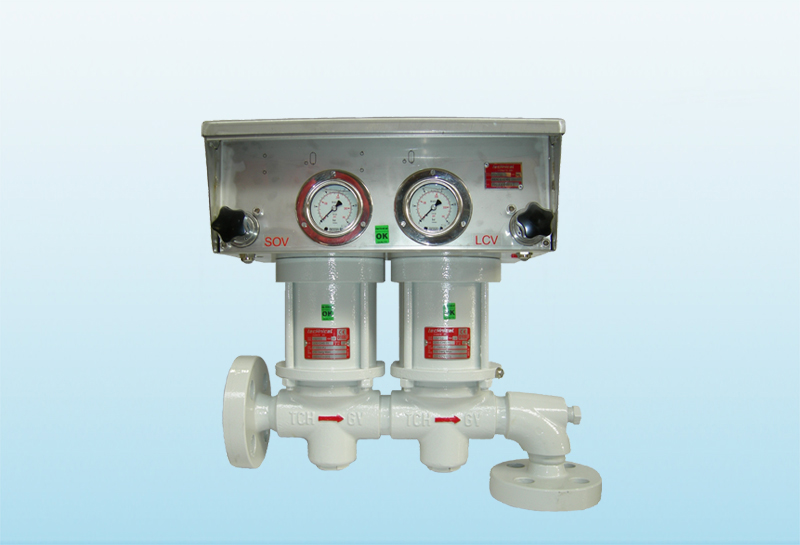
TECHNICAL offers a particular type of control valve to the Oil & Gas industry: the liquid discharge valve GV Series 20000 .
This valve are gate type, and are used mainly downstream of separators for discharge the water in excess.
The most request configuration is “solid block” which provides the coupling of the shut down valves and the control valve in a single block. The valves have integral single-acting actuator, and may be made of carbon steel or stainless steel. Their strength is constituted by the tungsten carbide seat that ensure a high wear resistance.
The proposal can also include a control panel that can be customized with limit switches, solenoid valves, pressure gauges and counter-strokes.
The materials, the sizes and the available connections allow interchangeability with the valves already on the ground.
All the control valves are PED certified.

TECHNICAL BROCHURE
USE AND MAINTENANCE MANUAL